
Modeling dislocations at the atomic scale
There are two major problems when simulating dislocations at the atomic scale.
The first one is due to the fact that all of the atoms in the crystal containing the dislocation are significantly displaced by its presence. Atoms far away from the core are always slightly displaced compared with atoms in a perfect reference crystal. Indeed, the long-range displacement field is proportional to 1/r. This means that the modelling approaches used to study point defects and surfaces, where the atomic structure away from the defect is identical to the structure of a perfect reference crystal, are not appropriate.
The second one is a consequence of the previous one. The cell sizes that are required to obtain convergence of the calculations are such that they involve a number of atoms that precludes first-principles calculations.
The various approaches to modelling dislocation cores described below side-step this issue in different ways. The cluster-based methods combine continuum elastic theory of the extended crystal with an atomistic model of the core. Dipole models seek to cancel the long-range elastic displacements by arranging for the simulation to contain several dislocations with zero net Burgers vector.
1) The displacement field of a dislocation
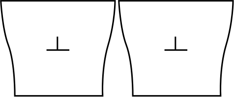
A dislocation is responsible for a long-range elastic field. When introducing a dislocation in a simulation box of finite size, the atomic planes at the boundaries are deformed. If we place two such boxes next to each other, the boundaries do not match and a region of void is found between two neighboring cells. This is illustrated below with an edge dislocation. It is of course unphysical, and such a naive construction cannot yield proper results.
2) The cluster approach
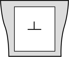
A first solution to this problem is to freeze the atom layers at the boundaries of the simulation box, as illustrated below. By doing so, the long-range elastic field of the dislocation is maintained fixed and cannot evolve during the simulation, but the atoms inside the box can. Such a setup allows to model and study the core structure of an isolated dislocation.
This setup is however not suited to the study of dislocation motion. Indeed, if the dislocation moves it will get closer to a boundary. Since the boundaries are fixed the long-range elastic field of the dislocation will become wrong, and a spurious interaction between the fixed boundaries and the moving dislocation will make difficult the evaluation of a Peierls barrier. In addition the dislocation will not be able to move across the fixed boundaries.
3) The periodic cluster approach
In the case of ionic materials, the fixed free surfaces can be charged, which would introduce an undesirable electric field inside the simulation. This can be solved by making the cluster periodic, so that positive and negative surfaces are close together and there is no net long-range electric field.
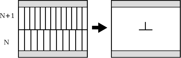
In order to study dislocation motion, it is possible to make the simulation periodic along the direction of glide. The figure below shows how an edge dislocation can be constructed: two systems are superimposed, the top one containing one more atomic plane than the bottom one. Then the top and bottom boundaries are fixed (shaded areas). After relaxation an edge dislocation is formed, and the system is periodic along the glide direction (Chap.4 in Bulatov & Cai, 2006).
In the RheoMan project we used such a periodic cluster approach to determine the Peierls stress of edge and screw dislocations in MgSiO3 (P. Hirel et al., Acta Mater. 79 (2014) 117-119).
One must bear in mind that the atom positions in the frozen top and bottom regions (shaded areas) do not correspond to the true long-range elastic field of the dislocation. This will result in spurious interactions if the dislocation moves far from its original position.
4) The 3-D periodic boundary conditions
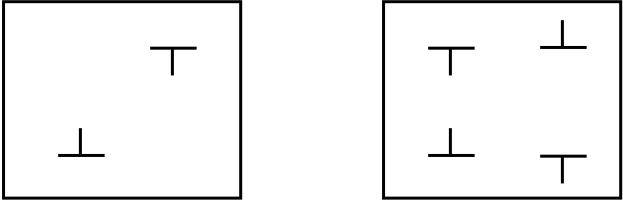
The undesirable effects of fixed boundaries can be removed when a dipole or a quadrupole of dislocations is inserted in the simulation, as illustrated below. At long range the combined elastic fields of the two (or four) dislocations vanish, and 3-D periodic boundary conditions can be used. No atom need to be frozen.
Such a simulation setup allows to study dislocation motion. In the RheoMan project, we are currently using this approach to compute the activation energy for the migration of screw dislocations in MgSiO3, using the nudged elastic band (NEB) method.
This approach can require large simulation cells to minimize the interactions between neighboring dislocations. Indeed, dislocations of opposite signs attract each other, and if they are too close they may annihilate, leaving only a supercell of perfect crystal. If the dislocations have a very wide core structure, in particular dissociated dislocations, then very large supercells may be required, as it is the case in some metals or perovskite materials (SrTiO3).
References:
V. Bulatov & W. Cai (2006) Computer simulation of dislocations. Oxford University Press